Deep Dive: Design Tables
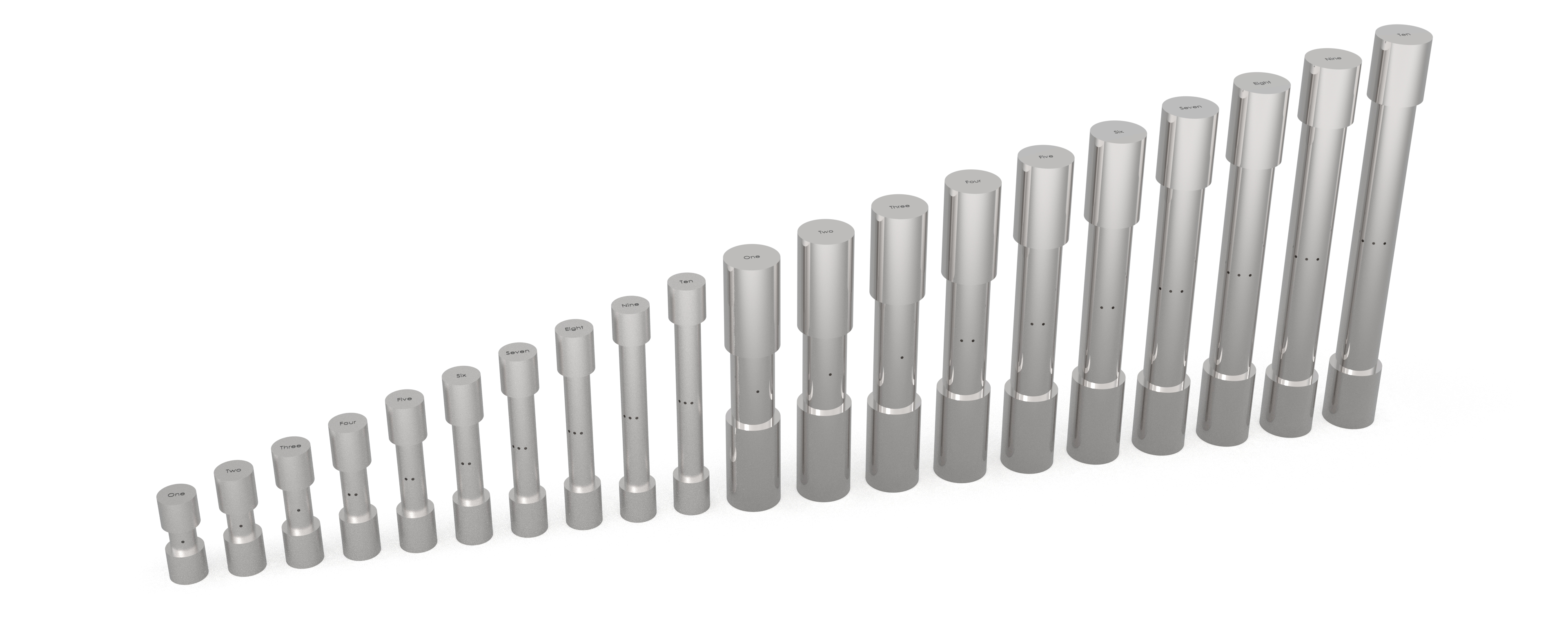
Using design tables is a proven practice for improving the management of complex parts and is one of the most powerful tools in SolidWorks (SW).
If your project requires multiple design configurations, creating them one by one is time consuming. Managing parameters across configurations that aren’t linked is cumbersome and slow. Opening each configuration to edit, updating individual features, or modifying sketches one at a time is prone to errors and is inefficient. As your configuration count increases all these challenges become more and more difficult to manage. Utilizing a design table can help eliminate frustrations and improve the design process.
What is a Design Table?
Design tables allow you to quickly create and manage multiple configurations within a single part file organized in an embedded Microsoft Excel worksheet. The spreadsheet may contain different information such as dimensions, parameters, feature statuses, materials, part numbers, and so on for each individual configuration. Leveraging this as a design tool allows you to capture several key benefits.
What are the Benefits?
Streamlined Design Process
Managing part parameters in the design table format simplifies the design process by reducing the need for separate models or drawings for each variant. For the designer this makes it easier to view, update, and manage information across all configurations at once. When a change is required, you can update the design table, and all configurations will be updated simultaneously, saving time and effort.
Consistency and Accuracy
Changes made in the design table automatically propagate to all related configurations, reducing the risk of errors and inconsistencies. Design tables can be easily imported into the drawing, linking dimensions and properties directly to the model. This eliminates manual table data entry that is both time consuming and error prone.
Enhanced Design Control
Design tables make it easy to create and manage customized versions of a product. You can quickly generate new configurations by adding rows to the table and specifying the unique parameters for each variant. Configuration properties can be controlled in the table to easily manage different descriptions, part numbers, materials, etc. Variables can also be added as configuration properties to form equations based on design requirements. This allows for flexible and dynamic adjustments to the design, enabling quick exploration of different design options.
Improved Collaboration
Design tables make it easier to collaborate on product design. Team members can see all configurations in one place, understand which parameters are variable and driving, and make informed decisions based on the entire range of designs.
Scalability
Design tables are scalable, allowing you to start with a few configurations and easily expand to include more as needed. This scalability supports the growth and evolution of your product line without requiring a complete redesign.
Cost Reduction
Design effort is always a key factor for considering the cost of a design program. By streamlining the design process and reducing the time needed to manage multiple configurations, design tables help in cutting down the overall design and development costs. Additionally, by designing a more scalable model from the outset, future changes to the product will be more efficient.
How to Create a Design Table
In the menu, select ‘Insert’.
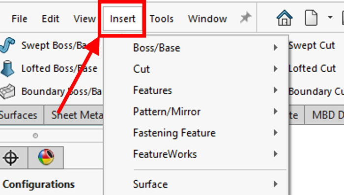
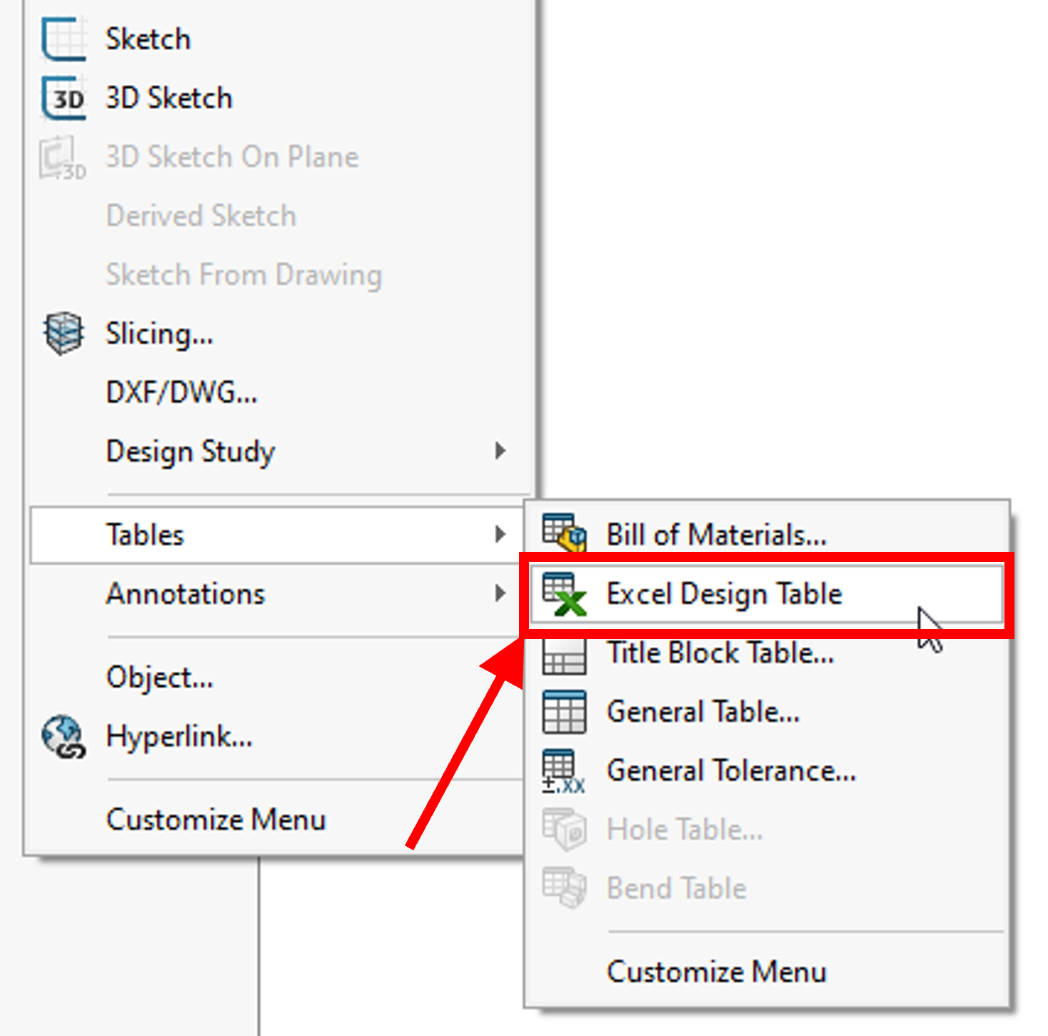
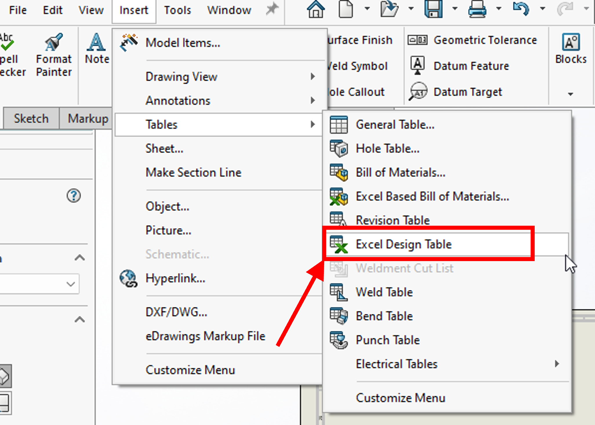
Hover the cursor over ‘Tables’ and select ‘Excel Design Table’ from the flyout menu.
When prompted use the following parameters: ‘Auto-Create’ for the Source selection, ‘Allow model edits to update the design table’ for Edit Control, and deselect ‘Enable cell drop-down lists’.
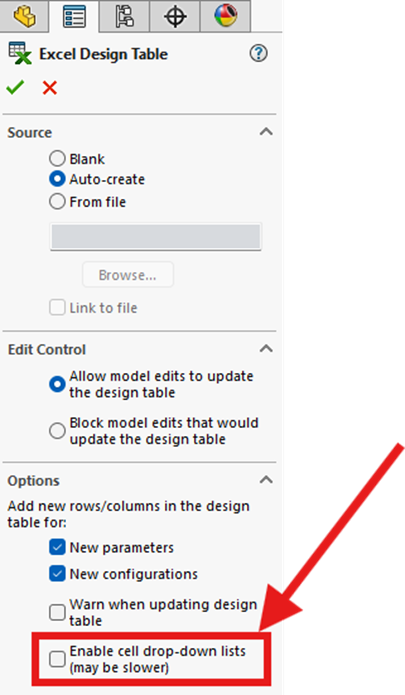
Once the ‘Check Mark’ is selected, SW will generate the Excel table and present it in a new window for editing.
Design Table Layout
When SW creates the design table the following information is auto-populated.
- Row 1: Referenced with “Design Table for: [Model File Name]”. Do not edit this line.
- Row 2: Parameter name. This is how SW references the information.
- Format is critical for a successful build, if this information isn’t formatted correctly, SW will fail to update the build with the information.
- SW starts the program at cell A2. This cell must remain blank and cannot be moved.
- Row 3+: List of all existing configurations along with the appropriate variable parameters.
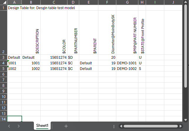
This table should be formatted in a way that is most beneficial for the designer managing the product. However, formatting information about parameters (Row 2) is critical to the design table working properly. It is recommended to not edit this row unless you are more familiar with manually adding or editing the parameters. Below is an outlines of how they are generally formatted.
- Dimensions: “[Dimension Name]@[Sketch/Feature Name]”
- Custom Properties: “$PRP@[Property Name]”
- State: “$STATE@[Sketch/Feature Name]”
Using Excel’s built-in formatting you should organize the table in a way the suits managing the data. Below are some best practices in laying out your design table.
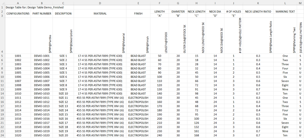
- Insert rows above Row 2 to create user friendly column labels. This will come in handy when importing this table into a drawing later.
- Layout the parameters in a fashion that helps with readability.
- When adding more than one or two configurations at a time, add them directly to the design table. Filling in rows below the first configuration will automatically create the configuration in the model and apply the parameters as entered.
- Custom properties such as materials and secondary operations can be managed within the design table.
- The state of particular features can also be managed; ‘U’=Unsuppressed and ‘S’=Suppressed.
- If you plan to use the design table in a drawing, you should consider organizing the columns as you would like the information to be presented in the drawing. More on that below.
Good Modeling Practices for Design Tables
There are a few key practices that are helpful to have in mind when creating and managing your model to improve the use of design tables.
- Rename the dimensions that you plan to control in the design table. This will help with knowing what dimensions are relevant when managing configurations.
- Rename the starting configuration(s) appropriately, this is typically done by part number, key size parameters, or some combination of the two.
- As mentioned, when creating a new design table, de-select “Enable cell drop-down lists (may be slower)”. Drop-down lists are rarely beneficial and increase processing time when creating a large number of configurations and parameters.
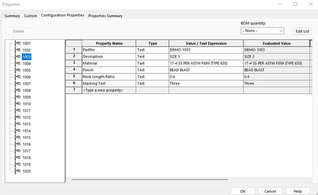
- Using the File Properties, add any custom properties you plan to control in the design table under the ‘Configuration Properties’ tab. As custom properties are edited they will populate back in the design table upon re-opening it.
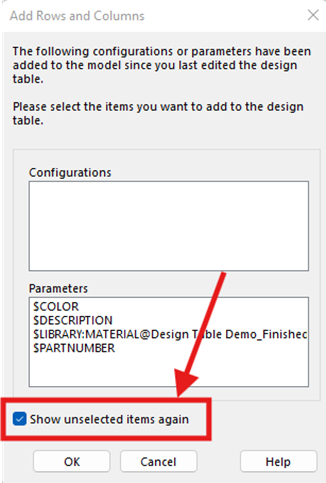
- When editing a design table, select ‘Show unselected items again’ if unsure about adding any listed configurations/parameters, so they can be added the next time you open the design table if desired.
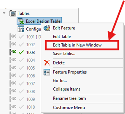
- When editing your design table in Excel, select ‘Edit Table in New Window’ vs within SW ‘Edit Table’ for better visibility and full excel formatting capabilities.
Using Design Tables in Drawings
As mentioned, one of the key benefits to leveraging design tables is using them in part drawings. Carrying this data into the drawing is straightforward and will ensure the parametric information that is in the model is accurate in the drawing.
Before creating a drawing, it is first important to format how SW will bring in the design table to the drawing. To do that first we will select ‘Edit Table’ in the configurations tab, not the previously mentioned ‘Edit Table in New Window’.
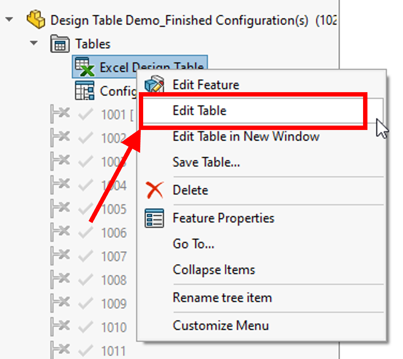
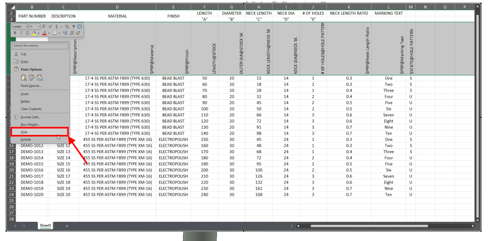
SW will present us with our table where we can begin to hide any rows or columns that we do not want to show in our drawing.
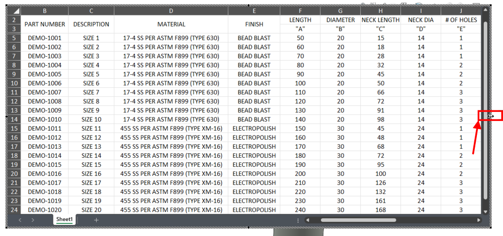
Next, we need to size the Excel window to what we want to be pulled into our drawing. Using the window handles, size the table such that only the relevant information is presented in the window. This will be important for when the table is imported into the drawing. This can also be useful for hiding columns or rows that shouldn’t be show in the drawing.
Create a new drawing and insert the model of interest so that SW is referencing the correct model.

With the model of interest is selected in the Drawing View, select ‘Insert’, hover over ‘Tables’, and select ‘Excel Design Table’. If a model is not selected here, the option for ‘Excel Design Table’ will be shown as unavailable.
Finally place design table can be placed within the drawing, presenting the necessary dimensions and parameters.
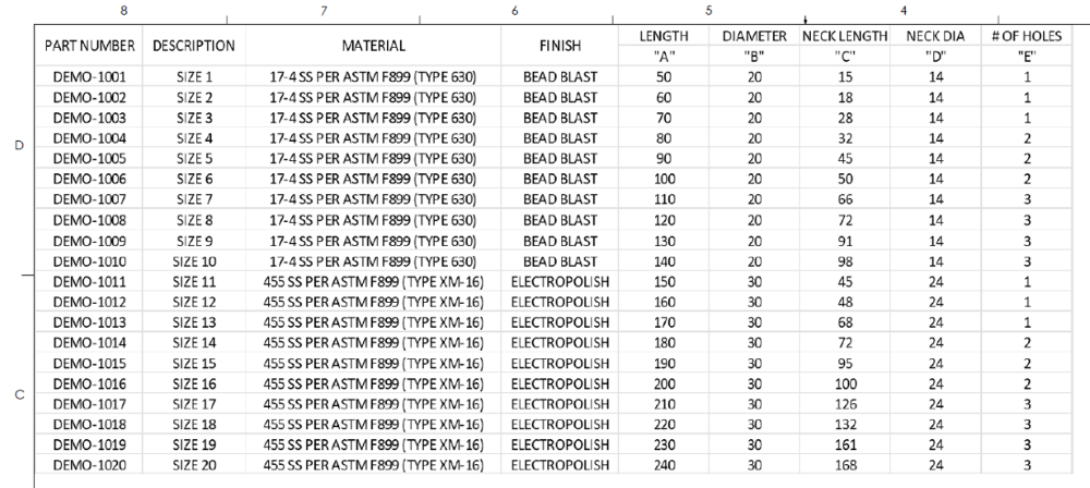
Updates made to the design table in the model will populate back into the drawing when saved or re-opened. When editing the design table in the future it will be important to repeat the process hiding the appropriate rows/columns as well as re-sizing the viewed table to ensure the drawing is updated correctly.
Summary
Leveraging the design table within SW is an effective way to save time and money on the design of a part with multiple configurations. The design table tool allows for a scalable model with many configurable parameters to be managed and updated effectively. This tool also ensures that the parametric information of the model is carried into the drawing, reducing errors and inaccuracies with manually entering information. The control of the design and collaboration across the project are improved from the increased transparency that the design table provides.
If you would like to learn more about the use of design tables and how to apply them, contact us today for a consultation.
